Opendesk at Autodesk
This article explores how we can integrate our configuration and distributed manufacturing systems with Autodesk’s collaborative, cloud-based design tools
We’re big fans of Autodesk. We use AutoCAD as a primary design tool and Inventor to master finished designs as parameterised applications. However, our current workflow isn’t particularly suitable for external designers to adopt: requiring rigorous adherence to a set of rather fragile mastering conventions.
So we were pretty excited to be invited by Autodesk to their cloud accelerator programme in Barcelona this week to explore how we could use their cloud-based Fusion 360 platform to build a workflow that would be much more accessible and designed from the ground up to support designer collaboration.
Fusion 360TM is the first 3D CAD, CAM, and CAE tool of its kind. It connects your entire product development process in a single cloud-based platform that works on both Mac and PC.
This diagram shows our vision of how open making will operate behind the scenes. CAD automation will aid every process from design authoring, customer specification and drawing generation for makers. We’ve already began to develop these tools and they’re explained in this post.
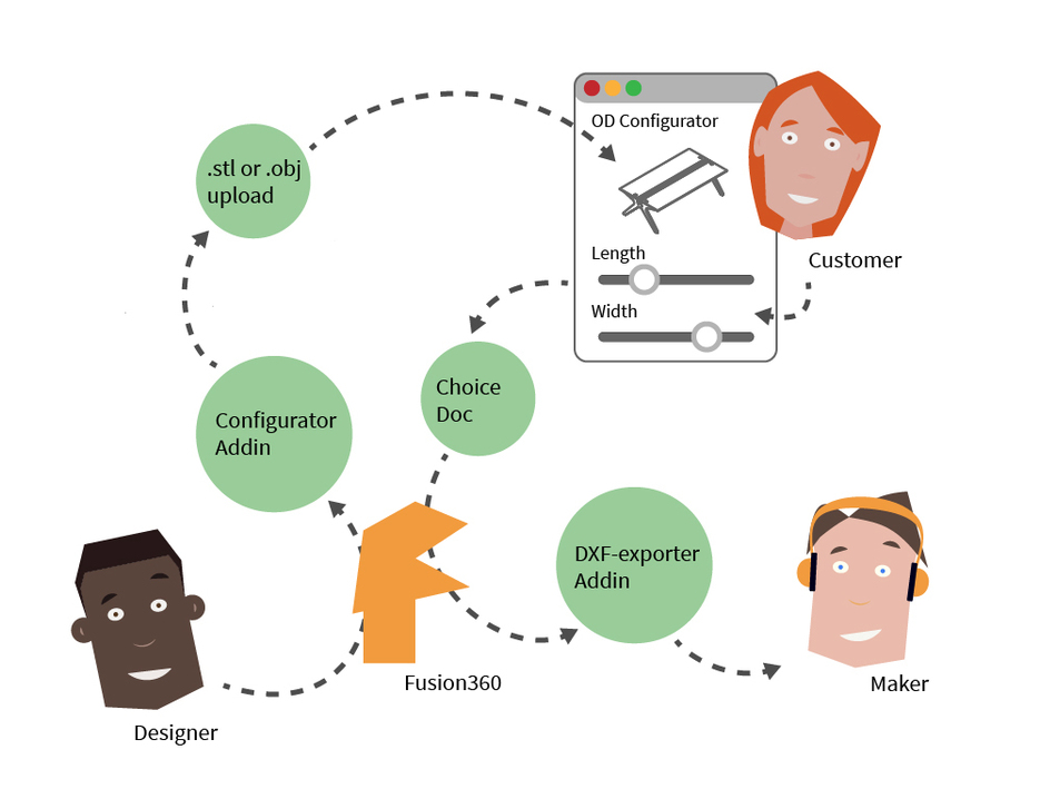
We were pretty confident that Fusion 360 would work as a design and mastering tool. Plus we could see that, just like Inventor, it came with a scriptable environment that we should be able to export files and data from. The key questions for us were whether we could crack the green bubbles shown in the diagram above and automate the export of:
- model data and parameterised rules to drive our in-browser customisation engine
- cutting files for makers to manufacture dynamically configured products
We felt that if we could crack these two technical issues, product designers all over the world could master designs in Fusion 360 and then export them for local manufacturing through our global maker network.
1. Diving In-browser Customisation
The challenge – automatically generating compatible data
As you can see from previous posts we’ve been looking into exposing our Inventor parameterised models for online configuration. Over the weeks leading up to the Autodesk accelerator, we’d developed a working prototype of an export-for-in-browser-customisation system. You can see a demo on opendesk-on-demand.firebaseapp.com and a technical note on the implementation approach here.
To very quickly summarise, this prototype system worked with:
- a 3D model exported from Inventor in
.objformat - a manually written
config.jsonfile that specified the parameters to expose and the geometric transformations to apply to the model when the parameter values changed
It then combined these into an intermediate data format (an obj.json document) which provided enough information for the in-browser customisation client to regenerate the 3D model in response to user input.
Our challenge was thus simple: could we get data out of Fusion 360 that we could coerce into the same format that our existing prototype system ran off?
The solution – courtesy of the Autodesk development team
The first difference we needed to overcome was a format problem: Fusion 360 can’t generate .obj files directly. However, it can generate ascii .stl files, which we could use in just the same way. So we started by porting our existing code from .obj to .stl, which turned out to be pretty straightforward.
That gave us the model data, which was the first half of the problem. The second half was to access the parameterisation data – the logical rules authored in Fusion 360 that control how the model geometry adapts to configurable variables like length, height etc – and coerce it to the right format. Now, using the Fusion 360 API we could access the rule data. However, once you’ve exported the geometry out in .stl format, you lose the mapping between the rules and the geometric components. I.e.: you know that rule X should be applied to component Y but there’s no obvious way of identifying component Y within the .stl file – without resorting to some kind of “are the coordinate values the same” hackery.
We were toying with the idea of writing our own exporter, which would thus be able to know which components were affected by which parameters. However, Adam, one of the Autodesk developers supporting us came up with a much more elegant solution.
We could manipulate the parameter values inside Fusion 360 and export multiple .stl files. A control file with the model’s default parameter values and a revised file per-parameter, generated after the value for that parameter had been changed. We could then compare the resulting files and determine which geometry values had changed: literally by comparing the two files line by line.
As it turned out, this technique worked perfectly, allowing us to automate the generation of parameterisation data in the same format that we’d previously been writing manually in our config.json file. The resulting system, which you can demo on opendesk-on-demand-fusion-360.firebaseapp.com works identically to our initial prototype but, crucially, automates the whole export process and should work with any generic Fusion 360 model – without requiring rigorous adherence to any fragile mastering conventions.
2. Cutting files for Makers
A major pain point for designers in the CNC fabrication process is how to communicate their designs effectively and consistently to makers. At Opendesk we have automated our internal drawing export process using Autodesk Inventor and AutoCAD. This automated process places geometry that represents tool paths on layers with standard layer names and line-specs making it incredibly easy for makers to read and understand the drawings of all Opendesk processed designs. Additionally, we’ve hooked this system up to our website allowing customers and makers to request customised Opendesk drawings and download them on demand. See this post for more info. To make this workflow easier to adopt we wanted to give all designers in our community the opportunity to automatically produce this standard format.
To achieve this we chose to develop another addin for the freely available Fusion 360 environment. The key aspect was to allow designers to work in their preferred CAD system, import solid models in to the Fusion environment and generate Opendesk standard drawings with a click of a button. Ultimately these drawings can quickly and easily be uploaded to the Opendesk network without the need for further internal processing.
Our current solution
With our Inventor based process we build a small library of individual parts and construct an assembly of the product, a nested assembly (where parts are “flattened” as if lying on a sheet of plywood) and an associated nested Inventor drawing. The Inventor addin iterates through parameters, updates assemblies and associated drawings each time before exporting the drawing in a .dxf format. The final drawing is finished by AutoCAD to turn individual line segments into closed loops that can be read by any CAM software.
During our week on the Forge Accelerator we decided to replicate and optimise this process. The addin can be run on any nested model built from bodies such as the Lean desk nested legs sheet.
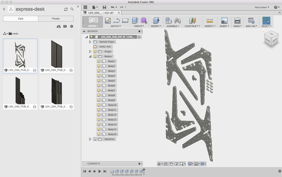
It works by iterating through each body in the model and stores the edge loop geometry and associated properties of each face. The properties of each of edge loop and associated face can be used to categorise the edge geometry in the standard Opendesk format, such as reverse face pockets or full depth through cuts. These categories map to specific layer conventions.
With the geometry data and layer information the addin writes the DXF text file directly without the need for an associated native drawing. This final step greatly optimises our initial Inventor process.
This addin achieves two things. One, designers can manually export Opendesk standard drawings. Two it completes the flow diagram at the top of this post by enabling on-demand drawing downloads. The configurator can communicate a choice document of parameter values to an instance of Fusion360 running the model. This model can be updated and the dxf exporter can generate the correct drawings.
Check this drawing exporter project out here
So, in summary, we were able to crack the two key technical issues that would allow us to adopt Fusion 360 and fully automate both the export for in-browser customisation and DXF cutting file generation. The next steps for us are to bring this online, probably first as an authoring tool for up-coming design challenges and then as an ongoing part of our design mastering and publishing workflow.
You can find the full source code and examples in the spike/fusion branch of our opendesk-on-demand GitHub repository.


