Parametric Design and Tailoring
How parametric design processes allow us to offer tailored products to the nearest millimetre.
The term ”parametric” originates from mathematics and refers to the use of certain parameters or variables that can be altered in order to manipulate the result of an equation. In furniture design, these equations can be used to alter the dimensions of a table, bench or any other product.
Antoni Gaudí created one of the earliest examples of parametric design with his design for the Church of Colònia Güell. Gaudi’s inverted model took inspiration from the architectural principle that an optimal arch follows an inverted Catenary Curve - an upside-down chain hanging under its own weight supported only at each end.
Using strings weighed down with birdshot Gaudi created complex vaulted ceilings and arches. By adjusting the position of the weights or the length of the strings he could alter the shape of each arch and interrogate dependencies in the building’s structure - how changing one arch would influence the arches connected to it.
Gaudi’s analogue method utilised the main features of computational parametric modelling processes that are common today - input parameters, equations driven by variables and end result/ output.


Parametric design can start with a conventional design asset like a drawing or 3D model. Key dimensions within the design can then be turned into parameters. By changing a parameter the design can be altered to extents which are pre-defined by the designer.
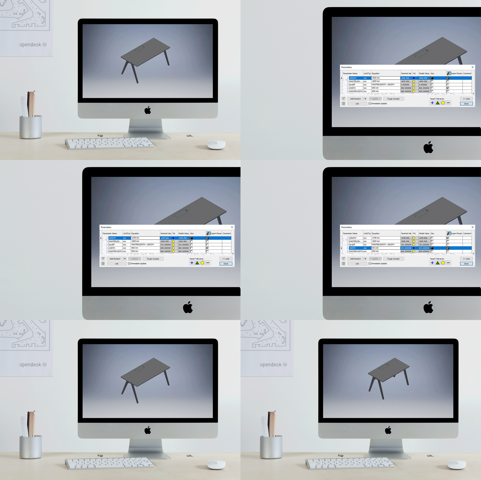
For example, the Studio Desk was originally designed to be a length of 1600mm and a width of 800mm. The length and width dimensions are defined and static. By making “length” and “width” a parameter, any number can be set and, with effective design logic, return a meaningful output. In this way, it’s possible to enter a length value of 1249mm and a width value of 691mm. Any part (e.g. the legs or tabletop) which respond to the parameters “length” and/or “width” will update accordingly resulting in a new instance of the Studio Desk. One parameter (e.g. length) may be used to drive equations within hundreds of parts.


Parametric design is an algorithmic process where parameters and rules are assembled to define the relationship between design intent and design response.
Without suitable design logic, the combination of parameter values can result in nonsensical outputs. It is the responsibility of the designer to define the boundaries within which their parametric design can operate. Real world consideration like load-bearing capacity, rigidity and the materials from which a design will be made inform these boundaries. The Studio Desk has a maximum length of 1600mm and a maximum width of 800mm for these reasons.
Parametric design consists of hierarchies in order to disseminate information through a design. Hierarchies are relationships between entities often described as parent and child. For example, the Studio Desk is the parent of multiple parts (children). The tabletop is a child of the Studio Desk. The cable cover which sits within the tabletop is a child of the tabletop. If a parameter within the parent changes, this information is fed through to parts which are dependent on the variable. Reducing the length of the Studio Desk requires design data to be disseminated to all children which respond based on the input/output of their parent.

Once a design’s parameters are defined, parts are laid flat and arranged within the borders of a 2440mm X 1220mm rectangle. This rectangle represents the material from which the Studio Desk will be made. This flat arrangement of parts is known as a nest.

2D projections of each 3D part within the nest are used to produce custom-made cutting files, on-demand, for each tailoring request we receive. These cutting files are issued to local manufacturers in .DXF format where they are used to produce toolpath files (files which tell a CNC machine how to cut parts) and cut on a CNC machine. Once cut, parts are assembled and finished by hand before the finished item is delivered to its new owner.


